The Kubelet and Service Proxy
The Kubelet
In a nutshell, the Kubelet is the component responsible for everything running on a worker node. Its initial job is to register the node it’s running on by creating a Node resource in the API server. Then it needs to continuously monitor the API server for Pods that have been scheduled to the node, and start the pod’s containers. It does this by telling the configured container runtime (which is Docker, CoreOS’ rkt, or something else) to run a container from a specific container image. The Kubelet then constantly monitors running containers and reports their status, events, and resource consumption to the API server.
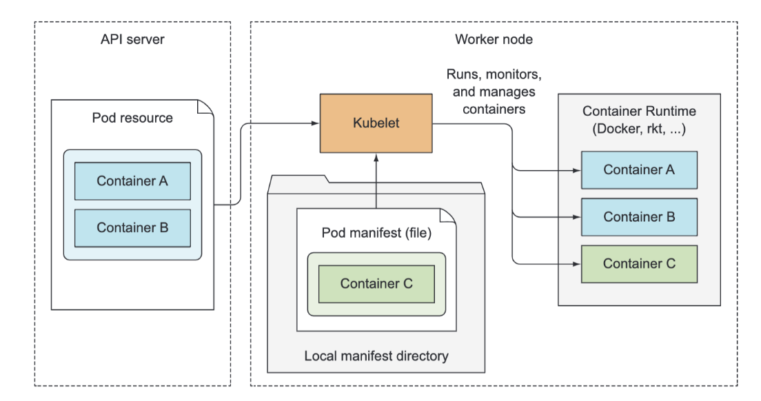
The Kubelet is also the component that runs the container liveness probes, restarting containers when the probes fail. Lastly, it terminates containers when their Pod is deleted from the API server and notifies the server that the pod has terminated.
Although the Kubelet talks to the Kubernetes API server and gets the pod manifests from there, it can also run pods based on pod manifest files in a specific local directory. This feature is used to run the containerized versions of the Control Plane components as pods. Instead of running Kubernetes system components natively, you can put their pod manifests into the Kubelet’s manifest directory and have the Kubelet run and manage them. You can also use the same method to run your custom system containers, but doing it through a DaemonSet is the recommended method.
The Service Proxy
Beside the Kubelet, every worker node also runs the kube-proxy, whose purpose is to make sure clients can connect to the services you define through the Kubernetes API. The kube-proxy makes sure connections to the service IP and port end up at one of the pods backing that service (or other, non-pod service endpoints). When a service is backed by more than one pod, the proxy performs load balancing across those pods.

The kube-proxy got its name because it was an actual proxy, but the current, much better performing implementation only uses iptables rules to redirect packets to a randomly selected backend pod without passing them through an actual proxy server. This mode is called the iptables proxy mode.
DNS Server
The DNS server pod is exposed through the kube-dns service, allowing the pod to be moved around the cluster, like any other pod. The service’s IP address is specified as the nameserver in the /etc/resolv.conf file inside every container deployed in the cluster. The kube-dns pod uses the API server’s watch mechanism to observe.
An Ingress controller runs a reverse proxy server (like Nginx, for example), and keeps it configured according to the Ingress, Service, and Endpoints resources defined in the cluster. The controller thus needs to observe those resources (again, through the watch mechanism) and change the proxy server’s config every time one of them changes. Although the Ingress resource’s definition points to a Service, Ingress controllers forward traffic to the service’s pod directly instead of going through the service IP. This affects the preservation of client IPs when external clients connect through the Ingress controller, which makes them preferred over Services in certain use cases.
Understanding The Components Involved in Deploying a Pod
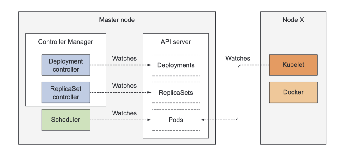
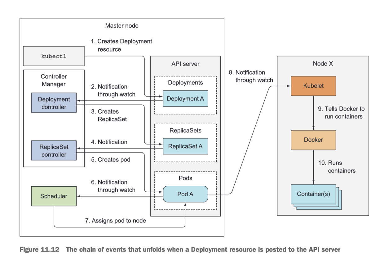
Imagine you prepared the YAML file containing the Deployment manifest and you’re about to submit it to Kubernetes through kubectl.
Kubectl sends the manifest to the Kubernetes API server in an HTTP POST request.
The API server validates the Deployment specification, stores it in etcd, and returns a response to kubectl.
Now a chain of events starts to unfold, as shown below:
The Pod Infrastructure Container
If you run a pod, and SSH onto the node and do a docker ps, you will see your container you ran, but also a “/pause” container. Judging from the COMMAND column, this additional container isn’t doing anything (the container’s command is "pause"). If you look closely, you’ll see that this container was created a few seconds before your container. What’s its role?
This pause container is the container that holds all the containers of a pod together. Remember how all containers of a pod share the same network and other Linux namespaces? The pause container is an infrastructure container whose sole purpose is to hold all these namespaces. All other user-defined containers of the pod then use the namespaces of the pod infrastructure container.
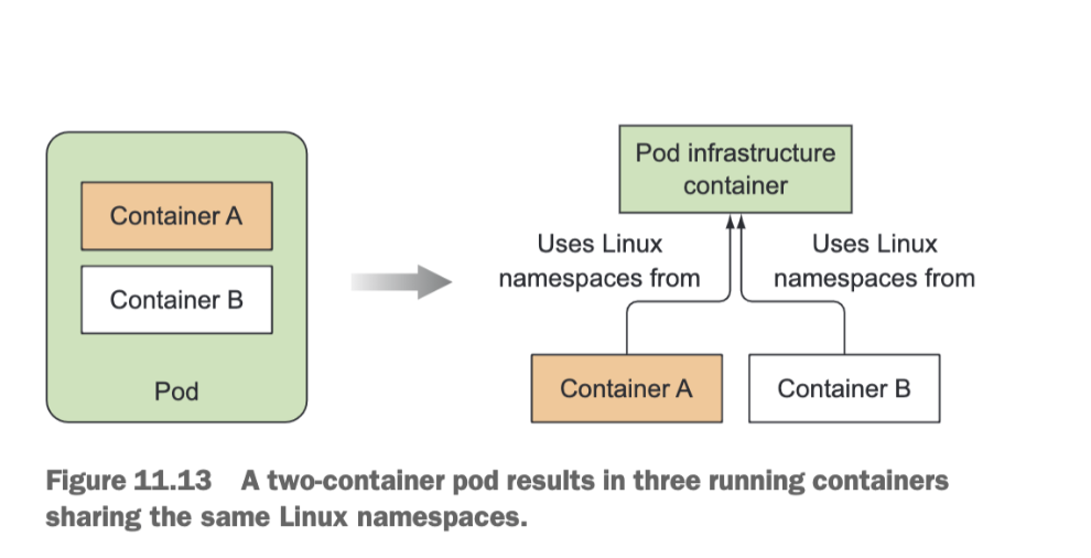
Actual application containers may die and get restarted. When such a container starts up again, it needs to become part of the same Linux namespaces as before. The infrastructure container makes this possible since its lifecycle is tied to that of the pod—the container runs from the time the pod is scheduled until the pod is deleted. If the infrastructure pod is killed in the meantime, the Kubelet recreates it and all the pod’s containers.
Pod Networking
Kubernetes does mandate that the pods (or to be more precise, their containers) can communicate with each other, regardless if they’re running on the same worker node or not. The network the pods use to communicate must be such that the IP address a pod sees as its own is the exact same address that all other pods see as the IP address of the pod in question. When pod A connects to (sends a network packet to) pod B, the source IP pod B sees must be the same IP that pod A sees as its own. There should be no network address translation (NAT) performed in between—the packet sent by pod A must reach pod B with both the source and destination address unchanged. This is important, because it makes networking for applications running inside pods simple and exactly as if they were running on machines connected to the same network switch. The absence of NAT between pods enables applications running inside them to self-register in other pods.
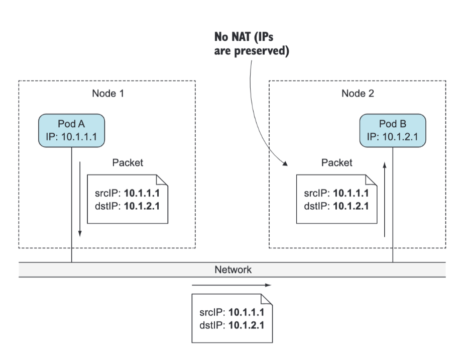
The requirement for NAT-less communication between pods also extends to pod-to-node and node-to-pod communication. But when a pod communicates with services out on the internet, the source IP of the packets the pod sends does need to be changed, because the pod’s IP is private. The source IP of outbound packets is changed to the host worker node’s IP address.
Communication Between Pods and the Same Node
Before the infrastructure container is started, a virtual Ethernet interface pair (a veth pair) is created for the container. One interface of the pair remains in the host’s namespace (you’ll see it listed as vethXXX when you run ifconfig on the node), whereas the other is moved into the container’s network namespace and renamed eth0. The two virtual interfaces are like two ends of a pipe (or like two network devices connected by an Ethernet cable) What goes in on one side comes out on the other, and vice-versa.
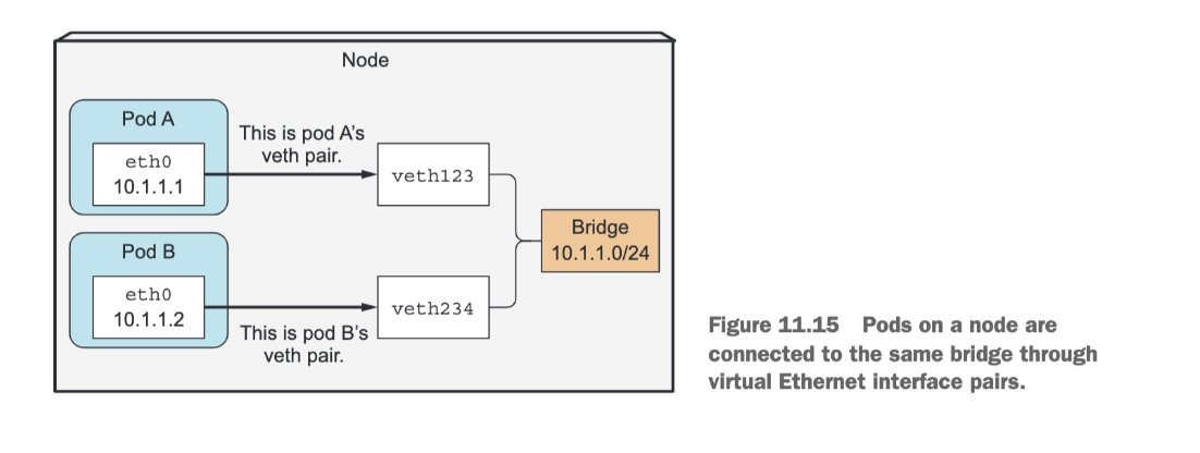
The interface in the host’s network namespace is attached to a network bridge that the container runtime is configured to use. The eth0 interface in the container is assigned an IP address from the bridge’s address range. Anything that an application running inside the container sends to the eth0 network interface (the one in the container’s namespace), comes out at the other veth interface in the host’s namespace and is sent to the bridge. This means it can be received by any network interface that’s connected to the bridge. If pod A sends a network packet to pod B, the packet first goes through pod A’s veth pair to the bridge and then through pod B’s veth pair. All containers on a node are connected to the same bridge, which means they can all communicate with each other. But to enable communication between containers running on different nodes, the bridges on those nodes need to be connected somehow.
Communication Between Pods On Different Nodes
You have many ways to connect bridges on different nodes. This can be done with overlay or underlay networks or by regular layer 3 routing. You know pod IP addresses must be unique across the whole cluster, so the bridges across the nodes must use non-overlapping address ranges to prevent pods on different nodes from getting the same IP. In the example, the bridge on node A is using the 10.1.1.0/24 IP range and the bridge on node B is using 10.1.2.0/24, which ensures no IP address conflicts exist. To enable communication between pods across two nodes with plain layer 3 networking, the node’s physical network interface needs to be connected to the bridge as well.
Routing tables on node A need to be configured so all packets destined for 10.1.2.0/24 are routed to node B, whereas node B’s routing tables need to be configured so packets sent to 10.1.1.0/24 are routed to node A. Packet first goes through the veth pair, then through the bridge to the node’s physical adapter, then over the wire to the other node’s physical adapter, through the other node’s bridge, and finally through the veth pair of the destination container.

Service Implementation
Each Service gets its own stable IP address and port. Clients (usually pods) use the service by connecting to this IP address and port. The IP address is virtual—it’s not assigned to any network interfaces and is never listed as either the source or the destination IP address in a network packet when the packet leaves the node. A key detail of Services is that they consist of an IP and port pair (or multiple IP and port pairs in the case of multi-port Services), so the service IP by itself doesn’t represent anything. That’s why you can’t ping them.
When a service is created in the API server, the virtual IP address is assigned to it immediately. Soon afterward, the API server notifies all kube-proxy agents running on the worker nodes that a new Service has been created. Then, each kube-proxy makes that service addressable on the node it’s running on. It does this by setting up a few iptables rules, which make sure each packet destined for the service IP/port pair is intercepted and its destination address modified, so the packet is redirected to one of the pods backing the service.
Besides watching the API server for changes to Services, the kube-proxy also watches for changes to Endpoints objects. An Endpoints object holds the IP/Port pairs of all the pods that back the service (an IP/port pair can also point to something other than a pod).That’s why the kube-proxy must also watch all Endpoints objects.
 The figure shows what the kube-proxy does and how a packet sent by a client pod reaches one of the pods backing the Service:
- The packet’s destination is initially set to the IP and port of the Service (in the example, the Service is at 172.30.0.1:80).
- Before being sent to the network, the packet is first handled by node A’s kernel according to the iptables rules set up on the node.
- The kernel checks if the packet matches any of those iptables rules.
- One of them says that if any packet has the destination IP equal to 172.30.0.1 and destination port equal to 80, the packet’s destination IP and port should be replaced with the IP and port of a randomly selected pod.
- The packet in the example matches that rule and so its destination IP/port is changed.
- In the example, pod B2 was randomly selected, so the packet’s destination IP is changed to 10.1.2.1 (pod B2’s IP) and the port to 8080 (the target port specified in the Service spec).
- From here on, it’s exactly as if the client pod had sent the packet to pod B directly instead of through the service.
Ingress and Egress Networking
Egress
Routing traffic from a Node to the public Internet is network specific and really depends on how your network is configured to publish traffic. To make this section more concrete I will use an AWS VPC to discuss any specific details. In AWS, a Kubernetes cluster runs within a VPC, where every Node is assigned a private IP address that is accessible from within the Kubernetes cluster. To make traffic accessible from outside the cluster, you attach an Internet gateway to your VPC.
- The Internet gateway serves two purposes: providing a target in your VPC route tables for traffic that can be routed to the Internet, and performing network address translation (NAT) for any instances that have been assigned public IP addresses.
- The NAT translation is responsible for changing the Node’s internal IP address that is private to the cluster to an external IP address that is available in the public Internet.
With an Internet gateway in place, VMs are free to route traffic to the Internet. Unfortunately, there is a small problem. Pods have their own IP address that is not the same as the IP address of the Node that hosts the Pod, and the NAT translation at the Internet gateway only works with VM IP addresses - because it does not have any knowledge about what Pods are running on which VMs (the gateway is not container aware). Let’s look at how Kubernetes solves this problem using iptables.
Life of a packet: Node to Internet
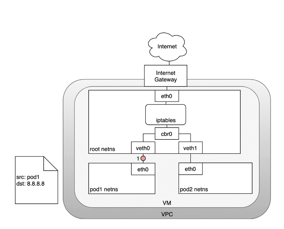
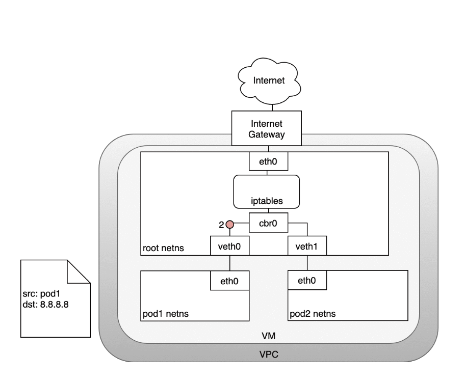
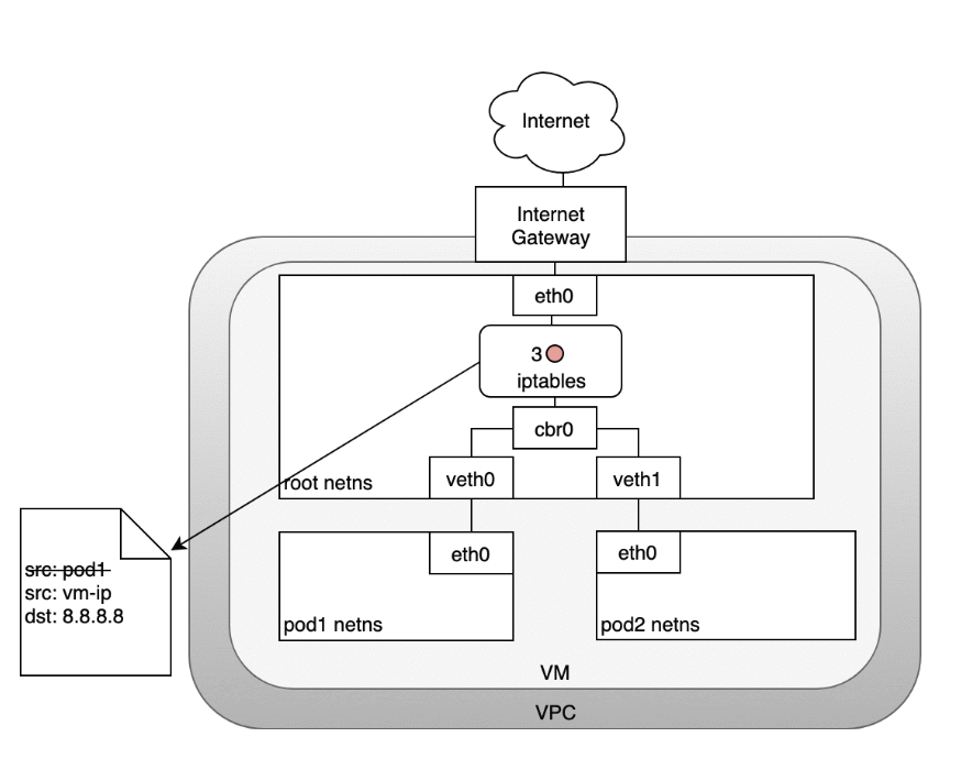
In the following diagram, the packet originates at the Pod’s namespace:- (1) and travels through the veth pair connected to the root namespace.
- (2) Once in the root namespace, the packet moves from the bridge to the default device since the IP on the packet does not match any network segment connected to the bridge. Before reaching the root namespace’s Ethernet device iptables mangles the packet.
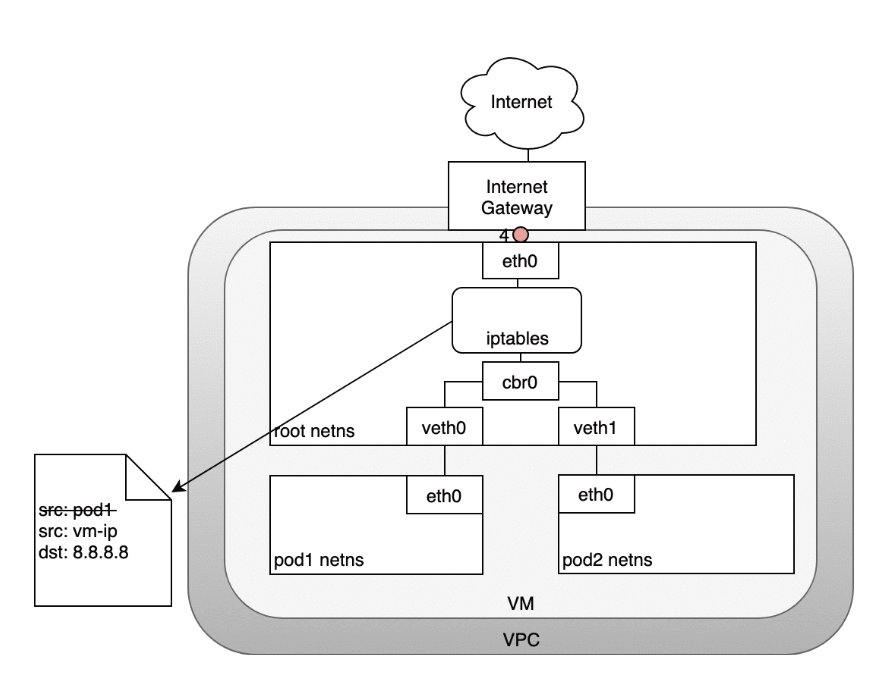
- (3) In this case, the source IP address of the packet is a Pod, and if we keep the source as a Pod the Internet gateway will reject it because the gateway NAT only understands IP addresses that are connected to VMs. The solution is to have iptables perform a source NAT — changing the packet source — so that the packet appears to be coming from the VM and not the Pod.
- (4) With the correct source IP in place, the packet can now leave the VM and reach the Internet gateway.
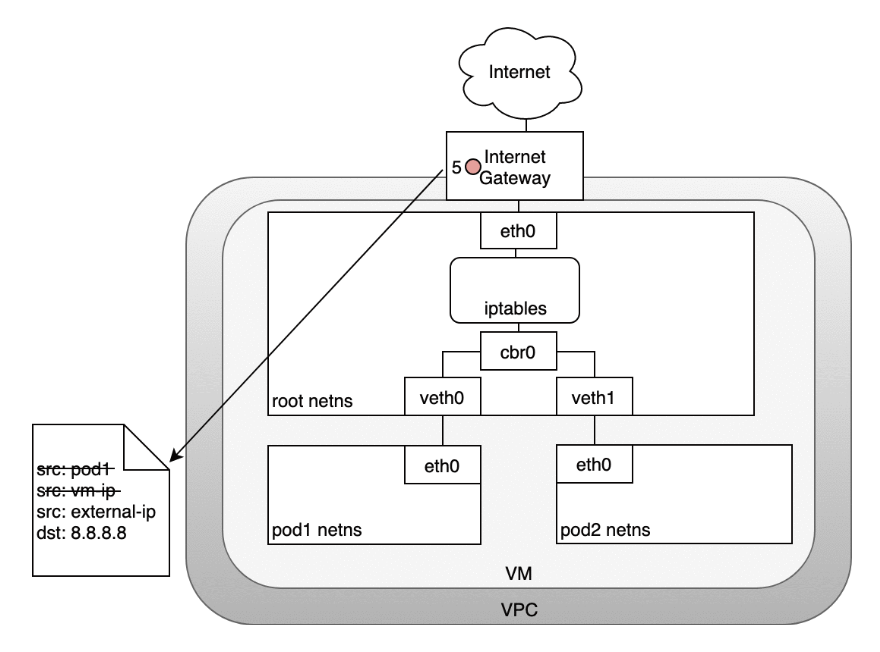
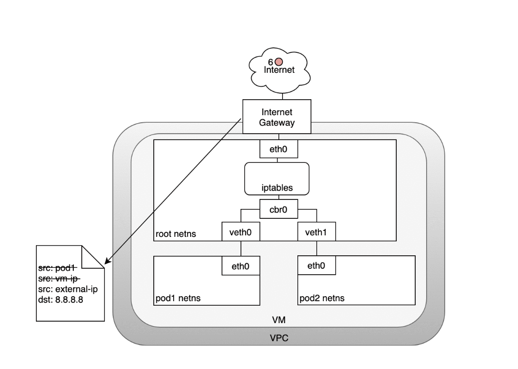
- (5) The Internet gateway will do another NAT rewriting the source IP from a VM internal IP to an external IP. Finally, the packet will reach the public Internet
- (6) On the way back, the packet follows the same path and any source IP mangling is undone so that each layer of the system receives the IP address that it understands: VM-internal at the Node or VM level, and a Pod IP within a Pod’s namespace.
Ingress
Ingress — getting traffic into your cluster — is a surprisingly tricky problem to solve. Again, this is specific to the network you are running, but in general, Ingress is divided into two solutions that work on different parts of the network stack: (1) a Service LoadBalancer and (2) an Ingress controller.
Layer 4 Ingress: LoadBalancer
When you create a Kubernetes Service you can optionally specify a LoadBalancer to go with it. The implementation of the LoadBalancer is provided by a cloud controller that knows how to create a load balancer for your service. Once your Service is created, it will advertise the IP address for the load balancer. As an end user, you can start directing traffic to the load balancer to begin communicating with your Service.
With AWS and GCP, load balancers are aware of Nodes within their Target Group of Target Pools (respectively) and will balance traffic throughout all of the Nodes in the cluster. Once traffic reaches a Node, the iptables rules previously installed throughout the cluster for your Service will ensure that traffic reaches the Pods for the Service you are interested in.
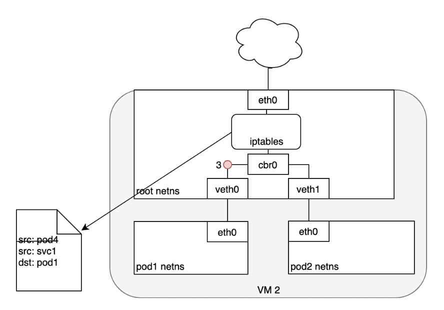
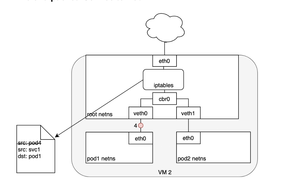
Life of a packet: LoadBalancer to Service
Let’s look at how this works in practice. Once you deploy your service, a new load balancer will be created for you by the cloud provider you are working with.
- (1) Because the load balancer is not container aware, once traffic reaches the load-balancer it is distributed throughout the VMs that make up your cluster.
- (2) iptables rules on each VM will direct incoming traffic from the load balancer to the correct Pod
- (3) — these are the same IP tables rules that were put in place during Service creation and discussed earlier. The response from the Pod to the client will return with the Pod’s IP, but the client needs to have the load balancer’s IP address. iptables and conntrack is used to rewrite the IPs correctly on the return path, as we saw earlier.
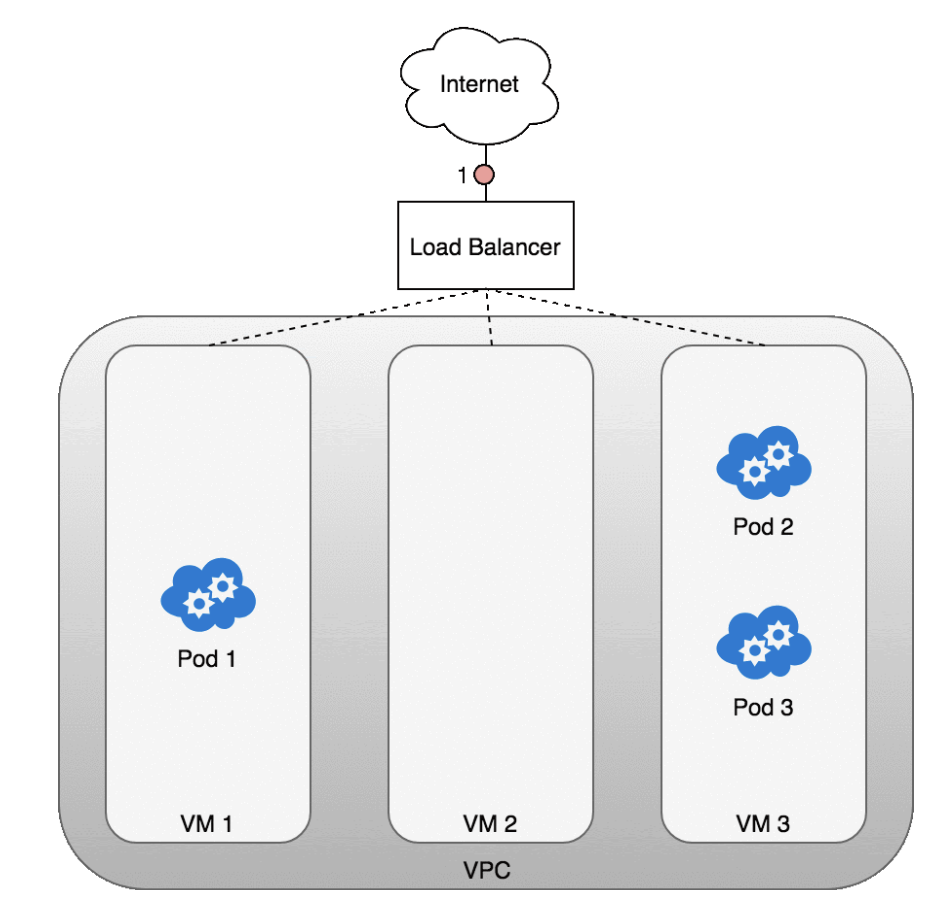
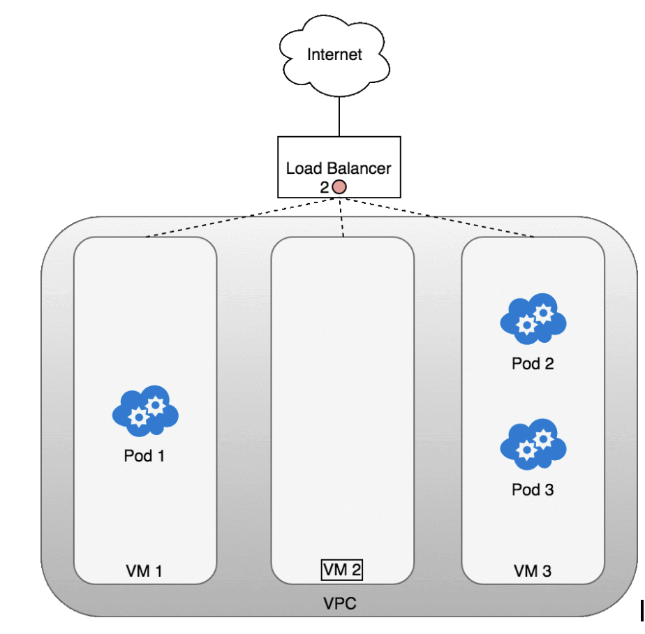
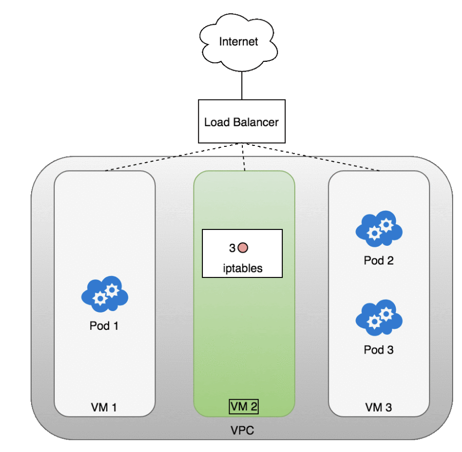
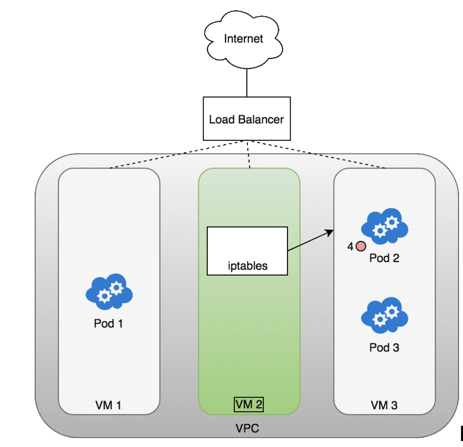
The following diagram shows a network load balancer in front of three VMs that host your Pods.
- Incoming traffic (1) is directed at the load balancer for your Service.
- Once the load balancer receives the packet (2) it picks a VM at random. In this case, we’ve chosen pathologically the VM with no Pod running: VM 2
- (3). Here, the iptables rules running on the VM will direct the packet to the correct Pod using the internal load balancing rules installed into the cluster using kube-proxy. iptables does the correct NAT and forwards the packet on to the correct Pod (4).
Packets sent from the Internet to a Service
Layer 7 Ingress: Ingress Controller
Layer 7 network Ingress operates on the HTTP/HTTPS protocol range of the network stack and is built on top of Services. The first step to enabling Ingress is to open a port on your Service using the NodePort Service type in Kubernetes. If you set the Service’s type field to NodePort, the Kubernetes master will allocate a port from a range you specify, and each Node will proxy that port (the same port number on every Node) into your Service. That is, any traffic directed to the Node’s port will be forwarded on to the service using iptables rules. This Service to Pod routing follows the same internal cluster load-balancing pattern we’ve already discussed when routing traffic from Services to Pods.
To expose a Node’s port to the Internet you use an Ingress object. An Ingress is a higher-level HTTP load balancer that maps HTTP requests to Kubernetes Services. The Ingress method will be different depending on how it is implemented by the Kubernetes cloud provider controller. HTTP load balancers, like Layer 4 network load balancers, only understand Node IPs (not Pod IPs) so traffic routing similarly leverages the internal load-balancing provided by the iptables rules installed on each Node by kube-proxy.
Within an AWS environment, the ALB Ingress Controller provides Kubernetes Ingress using Amazon’s Layer 7 Application Load Balancer. The following diagram details the AWS components this controller creates. It also demonstrates the route Ingress traffic takes from the ALB to the Kubernetes cluster.
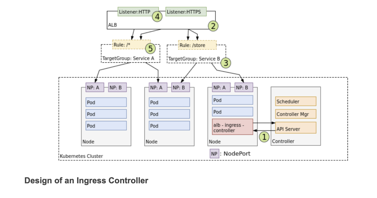
- When it finds Ingress resources that satisfy its requirements, it begins the creation of AWS resources.
- AWS uses an Application Load Balancer (ALB) (2) for Ingress resources. Load balancers work in conjunction with Target Groups that are used to route requests to one or more registered Nodes.
- (3) Target Groups are created in AWS for each unique Kubernetes Service described by the Ingress resource.
- (4) A Listener is an ALB process that checks for connection requests using the protocol and port that you configure.
- Listeners are created by the Ingress controller for every port detailed in your Ingress resource annotations.
- Lastly, Target Group Rules are created for each path specified in your Ingress resource. This ensures traffic to a specific path is routed to the correct Kubernetes Service (5).
Life of a packet: Ingress to Service
The life of a packet flowing through an Ingress is very similar to that of a LoadBalancer. The key differences are that an Ingress is aware of the URL’s path (allowing and can route traffic to services based on their path), and that the initial connection between the Ingress and the Node is through the port exposed on the Node for each service.
Let’s look at how this works in practice. Once you deploy your service, a new Ingress load balancer will be created for you by the cloud provider you are working with.- (1) Because the load balancer is not container aware, once traffic reaches the load-balancer it is distributed throughout the VMs that make up your cluster.
- (2) Through the advertised port for your service, iptables rules on each VM will direct incoming traffic from the load balancer to the correct Pod.
- (3) As we have seen before, the response from the Pod to the client will return with the Pod’s IP, but the client needs to have the load balancer’s IP address. Iptables and conntrack is used to rewrite the IPs correctly on the return path, as we saw earlier.
Packets sent from an Ingress to a Service
One benefit of Layer 7 load-balancers are that they are HTTP aware, so they know about URLs and paths. This allows you to segment your Service traffic by URL path.- They also typically provide the original client’s IP address in the X-Forwarded-For header of the HTTP request.
Pod to Service Networking
We’ve shown how to route traffic between Pods and their associated IP addresses. This works great until we need to deal with change. Pod IP addresses are not durable and will appear and disappear in response to scaling up or down, application crashes, or Node reboots. Each of these events can make the Pod IP address change without warning. Services were built into Kubernetes to address this problem.
A Kubernetes Service manages the state of a set of Pods, allowing you to track a set of Pod IP addresses that are dynamically changing over time.- Services act as an abstraction over Pods and assign a single virtual IP address to a group of Pod IP addresses.
- Any traffic addressed to the virtual IP of the Service will be routed to the set of Pods that are associated with the virtual IP.
- This allows the set of Pods associated with a Service to change at any time — clients only need to know the Service’s virtual IP, which does not change.
When creating a new Kubernetes Service, a new virtual IP (also known as a cluster IP) is created on your behalf. Anywhere within the cluster, traffic addressed to the virtual IP will be load-balanced to the set of backing Pods associated with the Service. In effect, Kubernetes automatically creates and maintains a distributed in-cluster load balancer that distributes traffic to a Service’s associated healthy Pods.
netfilter and iptables
- Netfilter is a framework provided by Linux that allows various networking-related operations to be implemented in the form of customized handlers.
- Netfilter offers various functions and operations for packet filtering, network address translation, and port translation, which provide the functionality required for directing packets through a network, as well as for providing the ability to prohibit packets from reaching sensitive locations within a computer network.
- In Kubernetes, iptables rules are configured by the kube-proxy controller that watches the Kubernetes API server for changes.
- When a change to a Service or Pod updates the virtual IP address of the Service or the IP address of a Pod, iptables rules are updated to correctly route traffic directed at a Service to a backing Pod.
- The iptables rules watch for traffic destined for a Service’s virtual IP and, on a match, a random Pod IP address is selected from the set of available Pods and the iptables rule changes the packet’s destination IP address from the Service’s virtual IP to the IP of the selected Pod.
- As Pods come up or down, the iptables ruleset is updated to reflect the changing state of the cluster. Put another way, iptables has done load-balancing on the machine to take traffic directed to a service’s IP to an actual pod’s IP.
IPVS
Kubernetes includes a second option for in-cluster load balancing: IPVS. IPVS (IP Virtual Server) is also built on top of netfilter and implements transport-layer load balancing as part of the Linux kernel. IPVS is incorporated into the LVS (Linux Virtual Server), where it runs on a host and acts as a load balancer in front of a cluster of real servers. IPVS can direct requests for TCP- and UDP-based services to the real servers, and make services of the real servers appear as virtual services on a single IP address. This makes IPVS a natural fit for Kubernetes Services.
When declaring a Kubernetes Service, you can specify whether or not you want in-cluster load balancing to be done using iptables or IPVS. IPVS is specifically designed for load balancing and uses more efficient data structures (hash tables), allowing for almost unlimited scale compared to iptables. When creating a Service load balanced with IPVS, three things happen: a dummy IPVS interface is created on the Node, the Service’s IP address is bound to the dummy IPVS interface, and IPVS servers are created for each Service IP address.
Expect IPVS to become the default method of in-cluster load-balancing. This change only affects in-cluster load-balancing and throughout the rest of this guide you can safely replace iptables with IPVS for in-cluster load balancing without affecting the rest of the discussion. Let’s now look at the life of a packet through an in-cluster load-balanced Service
Life of A Packet: Pod to Service
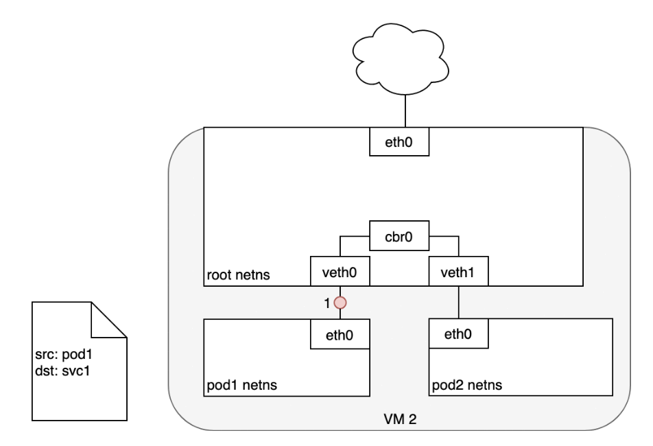
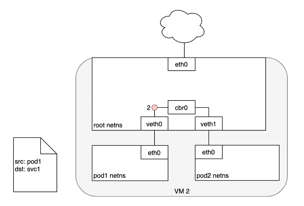
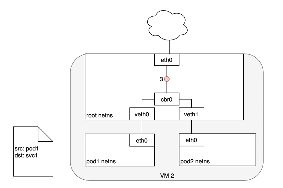
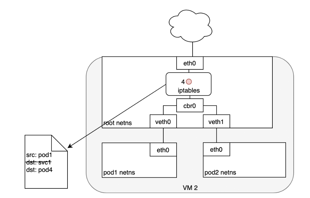
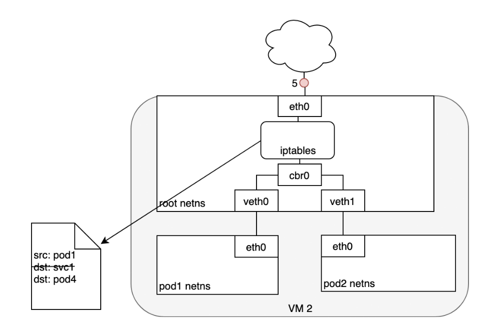
When routing a packet between a Pod and Service, the journey begins in the same way as before:- The packet first leaves the Pod through the eth0 interface attached to the Pod’s network namespace (1).
- Then it travels through the virtual Ethernet device to the bridge (2).
- The ARP protocol running on the bridge does not know about the Service and so it transfers the packet out through the default route — eth0 (3).
- Here, something different happens. Before being accepted at eth0, the packet is filtered through iptables.
- After receiving the packet, iptables uses the rules installed on the Node by kube-proxy in response to Service or Pod events to rewrite the destination of the packet from the Service IP to a specific Pod IP (4).
- The packet is now destined to reach Pod 4 rather than the Service’s virtual IP. The Linux kernel’s conntrack utility is leveraged by iptables to remember the Pod choice that was made so future traffic is routed to the same Pod (barring any scaling events).
- In essence, iptables has done in-cluster load balancing directly on the Node. Traffic then flows to the Pod using the Pod-to-Pod routing we’ve already examined (5).
Life of A Packet: Service to Pod
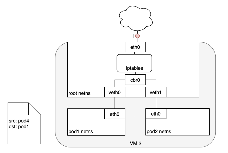
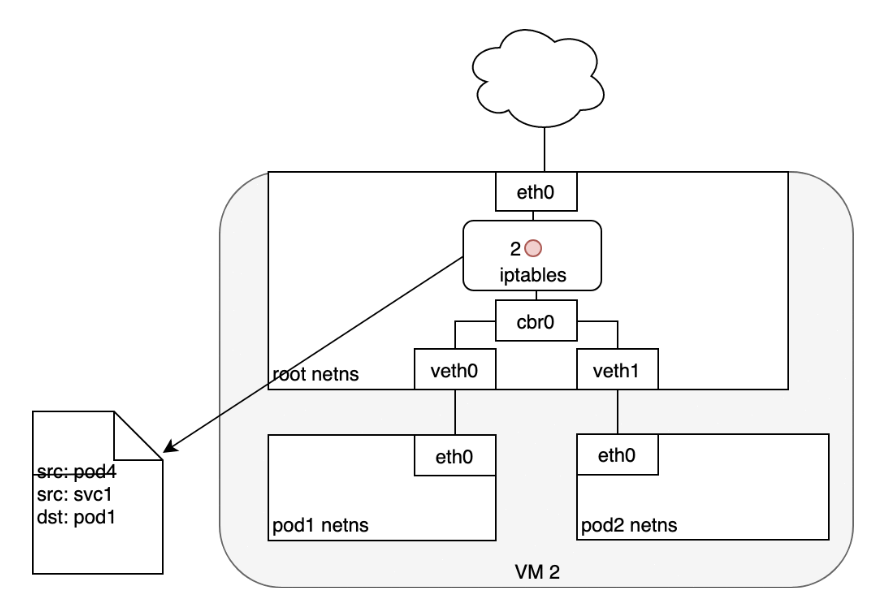
- (1) The Pod that receives this packet will respond, identifying the source IP as its own and the destination IP as the Pod that originally sent the packet.
- (2) Upon entry into the Node, the packet flows through iptables, which uses conntrack to remember the choice it previously made and rewrite the source of the packet to be the Service’s IP instead of the Pod’s IP.
- (3) From here, the packet flows through the bridge to the virtual Ethernet device paired with the Pod’s namespace.
- (4) And to the Pod’s Ethernet device as we’ve seen before.
Horizontally Scaling Apps and Leader-Election
To avoid the downtime, you need to run additional inactive replicas along with the active one and use a fast-acting lease or leader-election mechanism to make sure only one is active. In case you’re unfamiliar with leader election, it’s a way for multiple app instances running in a distributed environment to come to an agreement on which is the leader. That leader is either the only one performing tasks, while all others are waiting for the leader to fail and then becoming leaders themselves, or they can all be active, with the leader being the only instance performing writes, while all the others are providing read-only access to their data, for example. This ensures two instances are never doing the same job, if that would lead to unpredictable system behavior due to race conditions.
The mechanism doesn’t need to be incorporated into the app itself. You can use a sidecar container that performs all the leader-election operations and signals the main container when it should become active. You’ll find an example of leader election in Kubernetes at: https://github.com/kubernetes/contrib/tree/master/election.
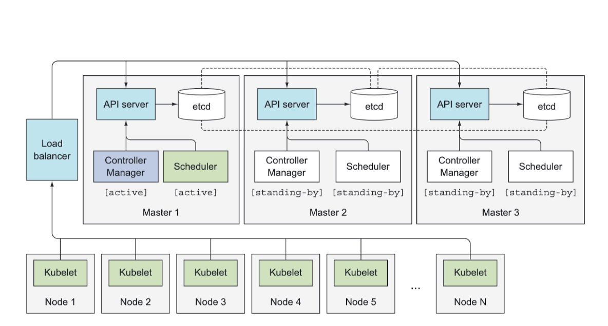
Ensuring your apps are highly available is relatively simple, because Kubernetes takes care of almost everything. But what if Kubernetes itself fails? What if the servers running the Kubernetes Control Plane components go down? How are those components made highly available?
Making The Control Plane Highly Available
Date Written: June 08, 2024