Intro
At the highest level, the architecture of Kubernetes consists of a Control Plane, and Data Plane. The architecture and framework of a control plane and data plane is not something new in networking, as it is a common architectural design pattern and the two most commonly referenced "planes" in networking. In networking, a plane is an abstract conception of where certain processes take place. The term is used in the sense of "plane of existence."
The control plane is the part of a network that controls how data packets are forwarded — meaning how data is sent from one place to another. In contrast to the control plane, which determines how packets should be forwarded, the data plane actually forwards the packets. (The data plane is also sometimes called the forwarding plane.)
Kubernetes has unique components that respectively reside in its control plane an data plane. All of which this blog post will explore more in detail. These main components are:
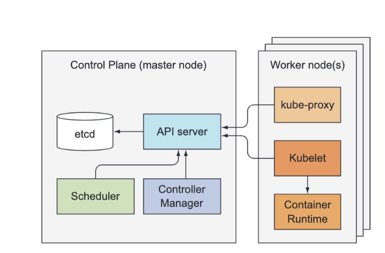
Kubernetes system components communicate only with the API server, meaning they don’t talk to each other directly. The API server is the only component that communicates with etcd. None of the other components communicate with etcd directly, but instead modify the cluster state by talking to the API server. Connections between the API server and the other components are almost always initiated by the components, but the API server does connect to the Kubelet when you use kubectl to fetch logs, use kubectl attach to connect to a running container, or use the kubectl port-forward command.
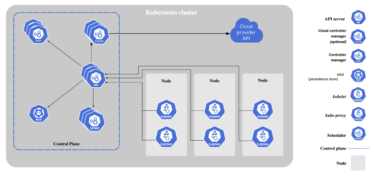
- Nodes: Nodes are VMs or physical servers that host containerized applications. Each node in a cluster can run one or more application instances. There can be as few as one node, however, a typical Kubernetes cluster will have several nodes (and deployments with hundreds or more nodes are not uncommon).
- Image Registry: Container images are kept in the registry and transferred to nodes by the control plane for execution in container pods.
- Pods: Pods are where containerized applications run. They can include one or more containers and are the smallest unit of deployment for applications in a Kubernetes cluster.
Kubernetes Control Plane And Data Plane Components
Kubernetes Control Plane Architecture
The control plane's components make global decisions about the cluster (for example, scheduling), as well as detecting and responding to cluster events (for example, starting up a new pod when a deployment's replicas field is unsatisfied). Control plane components can be run on any machine in the cluster. However, in all cloud provider setups (GCP, AWS, etc...), the control plane is hosted and controlled by the cloud provider. The Control plane holds and controls the state of the cluster, but does not run the app. Running the apps is done by the Worker Nodes.
A Kubernetes control plane is the control plane for a Kubernetes cluster. Its components include:
Kubernetes Node Architecture
Nodes are the machines, either VMs or physical servers, where Kubernetes place Pods to execute. Node components include:
Other Kubernetes Infrastructure Components
- Pods: By encapsulating one (or more) application containers, pods are the most basic execution unit of a Kubernetes application. Each Pod contains the code and storage resources required for execution and has its own IP address. Pods include configuration options as well. Typically, a Pod contains a single container or few containers that are coupled into an application or business function and that share a set of resources and data.
- Deployments: A method of deploying containerized application Pods. A desired state described in a Deployment will cause controllers to change the actual state of the cluster to achieve that state in an orderly manner. Learn more about Kubernetes Deployments.
- ReplicaSet: Ensures that a specified number of identical Pods are running at any given point in time.
- Cluster DNS: serves DNS records needed to operate Kubernetes services.
- Container Resource Monitoring: Captures and records container metrics in a central database.
Addons
Addons use Kubernetes resources (DaemonSet, Deployment, etc) to implement cluster features. Because these are providing cluster-level features, namespaced resources for addons belong within the kube-system namespace. There are many, but a few selected addons are described below:
Kubernetes Architecture Best Practices and Design Principles
Gartner’s Container Best Practices suggest a platform strategy that considers security, governance, monitoring, storage, networking, container lifecycle management and orchestration like Kubernetes. Here are some best practices for architecting Kubernetes clusters:
- Ensure you have updated to the latest Kubernetes version.
- Invest up-front in training for developer and operations teams.
- Establish governance enterprise-wide. Ensure tools and vendors are aligned and integrated with Kubernetes orchestration.
- Enhance security by integrating image-scanning processes as part of your CI/CD process, scanning during build and run phases. Open-source code pulled from a Github repository should always be considered suspect.
- Adopt role-based access control (RBAC) across the cluster. Least privilege, zero-trust models should be the standard.
- Further secure containers by using only non-root users and making the file system read-only.
- Avoid use of default value, since simple declaratives are less error-prone and demonstrate intent more clearly.
- Be careful when using basic Docker Hub images, which can contain malware or be bloated with unnecessary code. Start with lean, clean code and build packages up from there. Small images build faster, are smaller on disk, and image pulls are faster as well.
- Keep containers simple. One process per container will let the orchestrator report if that one process is healthy or not.
- When in doubt, crash. Kubernetes will restart a failed container, so do not restart on failure.
- Be verbose. Descriptive labels help current developers and will be invaluable to developers to follow in their footsteps.
- Don’t get too granular with microservices. Not every function within a logical code component need be its own microservice.
- Automate, where it makes sense. Automating CI/CD pipeline lets you avoid manual Kubernetes deployments entirely.
- Use livenessProbe and readinessProbe to help manage Pod lifecycles, or pods may end up being terminated while initializing or begin receiving user requests before they are ready.
Control Plane: Etcd
Pods, ReplicationControllers, Services, Secrets, and so on...need to be stored somewhere in a persistent manner so their manifests survive API server restarts and failures. For this, Kubernetes uses etcd, which is a fast, distributed and consistent key-value store.
Because it’s distributed, you can run more than one etcd instance to provide both high availability and better performance. The only component that talks to etcd directly is the Kubernetes API server. All other components read and write data to etcd indirectly through the API server. This brings a few benefits, among them a more robust optimistic locking system as well as validation; and, by abstracting away the actual storage mechanism from all the other components, it’s much simpler to replace it in the future. It’s worth emphasizing that etcd is the only place Kubernetes stores cluster state and metadata.
While multiple instances of etcd and API server can be active at the same time and do perform their jobs in parallel, only a single instance of the Scheduler and the Controller Manager may be active at a given time...with the others in standby mode.
The Kubelet is the only component that always runs as a regular system component, and it’s the Kubelet that then runs all the other components as pods. To run the Control Plane components as pods, the Kubelet is also deployed on the master. The next listing shows the pods in the kube-system namespace.
etcd v2 stores keys in a hierarchical key space, which makes key-value pairs similar to files in a file system. Each key in etcd is either:
- a directory, which contains other keys
- or is a regular key with a corresponding value. etcd v3 doesn’t support directories
Ensuring Consistency and Availability
Kubernetes requires all other Control Plane components to go through the API server. This way updates to the cluster state are always consistent, because the optimistic locking mechanism is implemented in a single place, so less chance exists, if any, of error. The API server also makes sure that the data written to the store is always valid and that changes to the data are only performed by authorized clients.
You’ll recognize that this is nothing other than a pod definition in JSON format. The API server stores the complete JSON representation of a resource in etcd. Because of etcd's hierarchical key space, you can think of all the stored resources as JSON files in a file system.
For ensuring high availability, you’ll usually run more than a single instance of etcd. Multiple etcd instances will need to remain consistent. Such a distributed system needs to reach a consensus on what the actual state is. etcd uses the RAFT consensus algorithm to achieve this, which ensures that at any given moment, each node’s state is either what the majority of the nodes agrees is the current state or is one of the previously agreed upon states.
Clients connecting to different nodes of an etcd cluster will either see the actual current state or one of the states from the past (in Kubernetes, the only etcd client is the API server, but there may be multiple instances). The consensus algorithm requires a majority (or quorum) for the cluster to progress to the next state. As a result, if the cluster splits into two disconnected groups of nodes, the state in the two groups can never diverge, because to transition from the previous state to the new one, there needs to be more than half of the nodes taking part in the state change. If one group contains the majority of all nodes, the other one obviously doesn’t. The first group can modify the cluster state, whereas the other one can’t. When the two groups reconnect, the second group can catch up with the state in the first group.
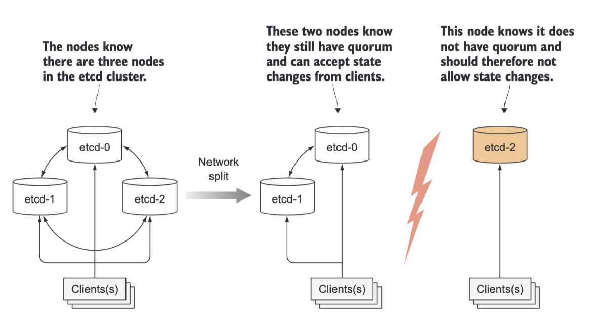 etcd is usually deployed with an odd number of instances. Comparing having (2) vs.having (1) instance:
- Having two instances requires both instances to be present to have a majority.
- If either of them fails, the etcd cluster can’t transition to a new state because no majority exists. Having two instances is worse than having only a single instance.
- By having two, the chance of the whole cluster failing has increased by 100%, compared to that of a single-node cluster failing.
- The same applies when comparing three vs. four etcd instances. With three instances, one instance can fail and a majority (of two) still exists.
- With four instances, you need three nodes for a majority (two aren’t enough). In both three- and four-instance clusters, only a single instance may fail.
- But when running four instances, if one fails, a higher possibility exists of an additional instance of the three remaining instances failing (compared to a three-node cluster with one failed node and two remaining nodes.
Control Plane: The API Server
First, the API server needs to authenticate the client sending the request. This is performed by one or more authentication plugins configured in the API server. The API server calls these plugins in turn, until one of them determines who is sending the request. It does this by inspecting the HTTP request.
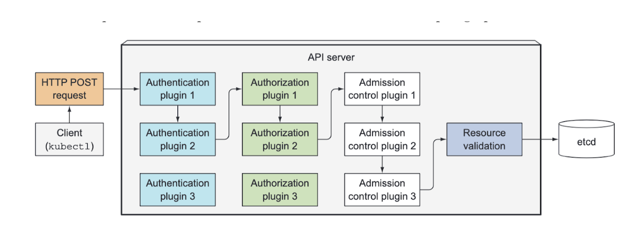
Besides authentication plugins, the API server is also configured to use one or more authorization plugins. Their job is to determine whether the authenticated user can perform the requested action on the requested resource. For example, when creating pods, the API server consults all authorization plugins in turn, to determine whether the user can create pods in the requested namespace. As soon as a plugin says the user can perform the action, the API server progresses to the next stage.
If the request is trying to create, modify, or delete a resource, the request is sent through Admission Control. Again, the server is configured with multiple Admission Control plugins. These plugins can modify the resource for different reasons. They may initialize fields missing from the resource specification to the configured default values or even override them. They may even modify other related resources, which aren’t in the request, and can also reject a request for whatever reason. The resource passes through all Admission Control plugins.
Examples of Admission Control plugins include:
The Api Server doesn’t create pods when you create a ReplicaSet resource and it doesn’t manage the endpoints of a service. That’s what controllers in the Controller Manager do. But the API server doesn’t even tell these controllers what to do. All it does is enable those controllers and other components to observe changes to deployed resources. A Control Plane component can request to be notified when a resource is created, modified, or deleted. This enables the component to perform whatever task it needs in response to a change of the cluster metadata. Clients watch for changes by opening an HTTP connection to the API server.
Through this connection, the client will then receive a stream of modifications to the watched objects. Every time an object is updated, the server sends the new version of the object to all connected clients watching the object.

Control Plane: The Scheduler
Control Plane: The Controller Manager
The Replication Manager
Control Plane: Other Controllers
The ReplicaSet, The DaemonSet, and Job Controllers
The ReplicaSet controller does almost the same thing as the Replication Manager described previously, so we don’t have much to add here. The DaemonSet and Job controllers are similar. They create Pod resources from the pod template defined in their respective resources. Like the Replication Manager, these controllers don’t run the pods, but post Pod definitions to the API server, letting the Kubelet create their containers and run them.
The Deployment Controller
The Deployment controller takes care of keeping the actual state of a deployment in sync with the desired state specified in the corresponding Deployment API object. The Deployment controller performs a rollout of a new version each time a Deployment object is modified (if the modification should affect the deployed pods). It does this by creating a ReplicaSet and then appropriately scaling both the old and the new ReplicaSet based on the strategy specified in the Deployment, until all the old pods have been replaced with new ones. It doesn’t create any pods directly.
The StatefulSet Controller
The StatefulSet controller, similarly to the ReplicaSet controller and other related controllers, creates, manages, and deletes Pods according to the spec of a StatefulSet resource. But while those other controllers only manage Pods, the StatefulSet controller also instantiates and manages PersistentVolumeClaims for each Pod instance.
The Node Controller
The Node controller manages the Node resources, which describe the cluster’s worker nodes. Among other things, a Node controller keeps the list of Node objects in sync with the actual list of machines running in the cluster. It also monitors each node’s health and evicts pods from unreachable nodes. The Node controller isn’t the only component making changes to Node objects. They’re also changed by the Kubelet, and can obviously also be modified by users through REST API calls.
The Service Controller
One of the services is the LoadBalancer service, which requests a load balancer from the infrastructure to make the service available externally. The Service controller is the one requesting and releasing a load balancer from the infrastructure, when a LoadBalancer-type Service is created or deleted.
The Endpoints Controller
Services aren’t linked directly to pods, but instead contain a list of endpoints (IPs and ports), which is created and updated either manually or automatically according to the pod selector defined on the Service. The Endpoints controller is the active component that keeps the endpoint list constantly updated with the IPs and ports of pods matching the label selector.
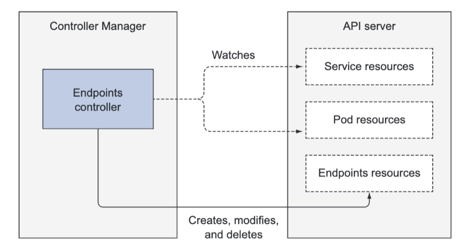
The controller watches both Services and Pods. When Services are added or updated or Pods are added, updated, or deleted, it selects Pods matching the Service’s pod selector and adds their IPs and ports to the Endpoints resource. Remember, the Endpoints object is a standalone object, so the controller creates it if necessary. Likewise, it also deletes the Endpoints object when the Service is deleted.
The Namespace Controller
When a Namespace resource is deleted, all the resources in that namespace must also be deleted. This is what the Namespace controller does. When it’s notified of the deletion of a Namespace object, it deletes all the resources belonging to the namespace through the API server.
The PersistentVolume Controller
Once a user creates a PersistentVolumeClaim, Kubernetes must find an appropriate PersistentVolume and bind it to the claim. This is performed by the PersistentVolume controller. When a PersistentVolumeClaim pops up, the controller finds the best match for the claim by selecting the smallest PersistentVolume with the access mode matching the one requested in the claim and the declared capacity above the capacity requested in the claim. It does this by keeping an ordered list of PersistentVolumes for each access mode by ascending capacity and returning the first volume from the list. Then, when the user deletes the PersistentVolumeClaim, the volume is unbound and reclaimed according to the volume’s reclaim policy (left as is, deleted, or emptied).
Again, all of these controllers operate on the API objects through the API server. They don’t communicate with the Kubelets directly or issue any kind of instructions to them. In fact, they don’t even know Kubelets exist. After a controller updates a resource in the API server, the Kubelets and Kubernetes Service Proxies, also oblivious of the controllers’ existence, perform their work, such as spinning up a pod’s containers and attaching network storage to them, or in the case of services, setting up the actual load balancing across pods.
Data Plane: The Kubelet and Service Proxy
The Kublet
In a nutshell, the Kubelet is the component responsible for everything running on a worker node. Its initial job is to register the node it’s running on by creating a Node resource in the API server. Then it needs to continuously monitor the API server for Pods that have been scheduled to the node, and start the pod’s containers. It does this by telling the configured container runtime (which is Docker, CoreOS’ rkt, or something else) to run a container from a specific container image. The Kubelet then constantly monitors running containers and reports their status, events, and resource consumption to the API server.
The Kubelet is also the component that runs the container liveness probes, restarting containers when the probes fail. Lastly, it terminates containers when their Pod is deleted from the API server and notifies the server that the pod has terminated.
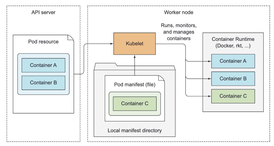
Although the Kubelet talks to the Kubernetes API server and gets the pod manifests from there, it can also run pods based on pod manifest files in a specific local directory as shown in figure 11.8. This feature is used to run the containerized versions of the Control Plane components as pods. Instead of running Kubernetes system components natively, you can put their pod manifests into the Kubelet’s manifest directory and have the Kubelet run and manage them. You can also use the same method to run your custom system containers, but doing it through a DaemonSet is the recommended method.
The Service Proxy
Beside the Kubelet, every worker node also runs the kube-proxy, whose purpose is to make sure clients can connect to the services you define through the Kubernetes API. The kube-proxy makes sure connections to the service IP and port end up at one of the pods backing that service (or other, non-pod service endpoints). When a service is backed by more than one pod, the proxy performs load balancing across those pods.

The kube-proxy got its name because it was an actual proxy, but the current, much better performing implementation only uses iptables rules to redirect packets to a randomly selected backend pod without passing them through an actual proxy server. This mode is called the iptables proxy mode.
The DNS server pod is exposed through the kube-dns service, allowing the pod to be moved around the cluster, like any other pod. The service’s IP address is specified as the nameserver in the /etc/resolv.conf file inside every container deployed in the cluster. The kube-dns pod uses the API server’s watch mechanism to observe.
An Ingress controller runs a reverse proxy server (like Nginx, for example), and keeps it configured according to the Ingress, Service, and Endpoints resources defined in the cluster. The controller thus needs to observe those resources (again, through the watch mechanism) and change the proxy server’s config every time one of them changes. Although the Ingress resource’s definition points to a Service, Ingress Controllers forward traffic to the service’s pod directly instead of going through the service IP. This affects the preservation of client IPs when external clients connect through the Ingress controller, which makes them preferred over Services in certain use cases.
Written: December 21, 2024